
Educational
Educational Events
Chiltern Model Steam Engines has been working with a couple of museums to develop materials that use the building of a model steam engine as a core educational activity. Using this "hands-on" activity, topics covered include an introduction to the history of steam engines, basic mechanics, the use of materials and manufacturing methods.
Using our kits and materials "How to make a steam engine" mini workshops are regularly run at the Blists Hill Victorian Town, Ironbridge.
Click to see the workshop session notes.
Longer sessions are also planned that go into more detail and include the history of steam from the industrial revolution using demonstrations and exhibits in the museums.
History of steam engines from the early industrial revolution.
Following the invention by the Marquis of Worcester of a steam device for raising water in 1663, notable contributions were made to the development of steam engines by Savery, Newcomen, Watt and many others.
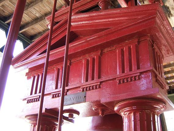
Some of the earliest engines were very crude and were often built into engine room walls. Later engines became more decorative and many reflected the Victorian genius for artistically ornate yet functional craftsmanship; Egyptian-style lotus-headed columns, fluted Doric columns and Corinthian and Gothic styles were among those introduced. Beam engines with these classical styles can still be seen today at for example Blists Hill, Iron Bridge Trust Museum.
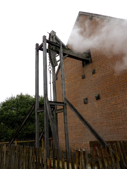
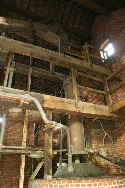
Very early steam engines used atmospheric pressure to move a beam up and down. This motion was used to drive pumps that removed water from mines - a big problem at the time. A replica Newcomen Engine can be seen at the Black Country Living Museum in Dudley, West Midlands.
As manufacturing techniques improved, engines evolved to use much higher steam pressure to push the piston which was by then connected directly to a flywheel in a more compact arrangement. These later more compact high pressure steam engines were used in a huge variety of applications such as manufacturing, through agriculture to transport.
This Youtube video of a steam engine driving a mining pit winch was taken at Blists Hill, Iron Bridge Trust Museum.
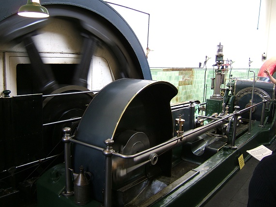
The Mill Engine at Queen Street Mill Textile Museum, Burnley.
Steam engines of different forms continued to be used in large numbers right into the twentieth century when they were gradually replaced by internal combustion and turbine engines.
How steam engines Work - it's all about hot water.
Water, when heated, stores latent energy which is then released when it reaches boiling point and is hence converted into steam. If heated in an open container the water boils at 100°C and as water expands when it turns into steam, around half a litre of water turns into nearly 1000 litres of steam. In the open this expansive force of steam just escapes freely to the atmosphere without doing any useful work.
However, if steam is generated in an enclosed boiler from which it cannot easily escape,
the expansion generates pressure. It is this pressure when the steam is released which is used to drive steam engines.
A pipe is used to connect the boiler to the engine along which the steam flows under pressure to the engine's cylinder. The cylinder is a hollow metal tube inside which is a plunger called a piston.
Beam Engines
In early atmospheric or beam engines the piston is connected via a rod or shaft to one end of an off balance pivoted beam. When the piston is at the top of its stroke steam is pushed into the cylinder and then condensed (turned back into water) by a jet of cold water. As mentioned earlier, water takes up a fraction of the space of steam, so this creates a vacuum and allows the piston to be pushed down again by the pressure of the atmosphere. The beam is also pulled down by the piston but when the piston is at the bottom of the cylinder the beam, now off balance, pulls the piston back up to the top allowing the cycle to start again.
The beam is also connected to a pump, often a simple plunger and valve arrangement.
Also see this animation.
The original Newcomen engines were developed to be more efficient and powerful, See this web site page by Carl Lira.
High Pressure Steam Engines
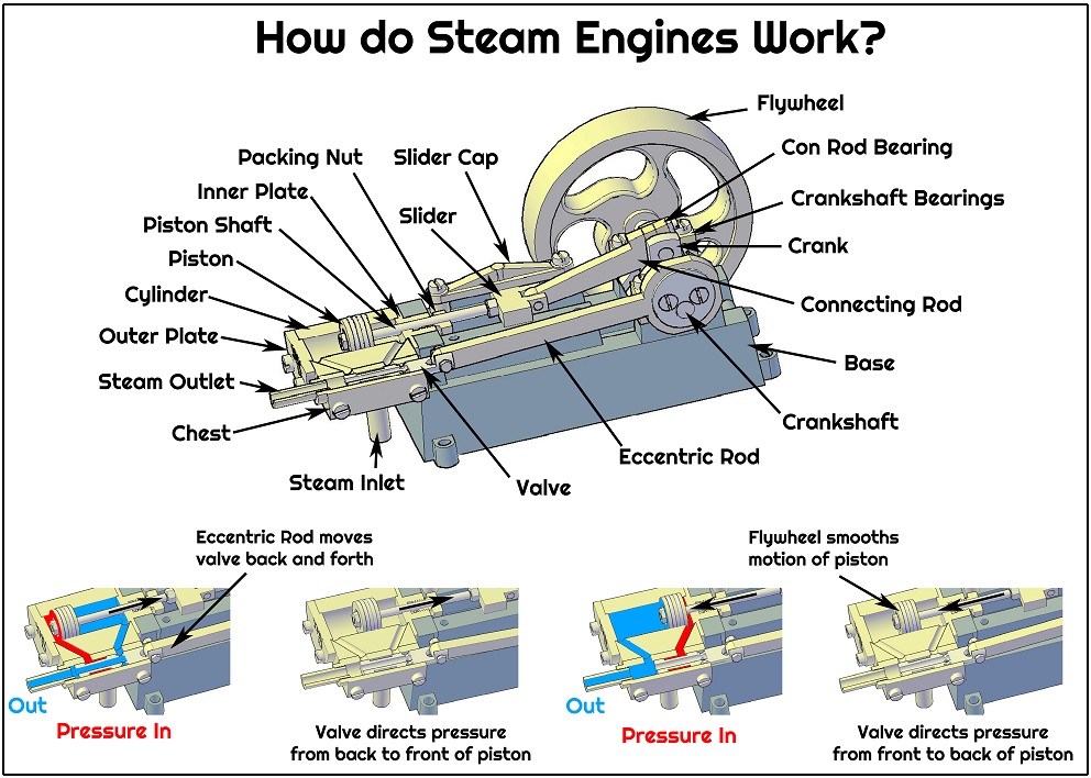
In later engines, such as those developed in 1800 by Richard Trevithick, much higher pressure steam from the boiler moves the piston, which in turn pushes or pulls a crank which in turn rotates a flywheel. A valve between the boiler and the engine is used to direct the steam alternatively to the front and back of the piston so that the flywheel continues to rotate. The angular momentum of the flywheel moves the piston at the end of its stroke when there is no steam pressure and provides smooth power output to whatever the engine is driving.
see this Youtube video and this animation.
Cutaway diagram of The Chiltern Model Steam Single Cylinder Mill Engine (click on image for A2 Poster)
How steam engines are made - some of the methods used
We will use how our model steam engines are made to give you an overview of the different manufacturing methods or process used.
The overall process, As with any item you may wish to make is; design, prototype, manufacture, test/rectify, commission (put into operation) and maintain for its life.
Design and Prototype
Design is the first stage and needs to the completed before anything is physically produced. Based on research into how steam engines would work and the necessary components or parts that would make up the engine, the engineer produced detailed information for each of the parts that would be needed by the workers to make those parts.
Traditionally this is done using a "technical drawing" which includes precise dimensions of the different parts. Technical drawing is done using pen or pencil and paper on large drawing boards with rulers, set squares, etc. It is easy to make mistakes in a drawing so they should always be checked by other engineers before any expensive parts are made using the drawings.
Ultimately however the parts need to be made to ensure they fit together and work as envisaged. The initial parts made are called prototypes and are used to make changes or corrections to the drawings. Design changes are often also made so that the final production parts can be made more efficiently. This traditional design process was very time consuming, costly and error prone.
Computers have made a big difference to how designs are produced in particular how the different parts fit together. Parts can be represented or modeled virtually in 3D (3 dimensions rather than the 2 of a paper drawing) and many more problems or errors corrected by the design engineer before any physical parts are made, hence speeding up the process amd reducing costs. The design or CAD (Computer Aided Design) computers can also send information directly to the CAM (Computer Aided Manufacture) computers controlling the machines which make the parts - these are often called CNC (Computer Numerical Control) machines. This also speeds up the process and reduces errors.
The designs for the Chiltern Model Steam engines were produced on a computer using CAD software and detailed 3D information about the parts sent electronically to the manufacturer who made the parts on CNC machines.
Manufacture
There are 60 parts in our stream engine, including all the screws, made of different types of metal. Looking at some examples:
Base - cast Mild Steel (as this is the best way to make complex shapes), machined on a milling machine, holes drilled and tapped, filed then cleaned and eventually painted.
Cylinder - cast brass, machined in a milling machine, holes drilled and tapped, bore reamed to size, filed then cleaned and eventually polished.
Bearings - cast bronze, machined in a milling machine, holes drilled and bore reamed size.
Valve and Piston Shaft - machined Stainless Steel in a lathe and milling machine, threaded and holes drilled.
Eccentric Rod - punched out of 4mm brass sheet, machined in a milling machine and holes drilled.
Casting
There are many different types, the one we used here is called lost wax or investment casting in which molten metal is poured into an expendable (used one) ceramic mould. It is a very old technique going back thousands of years up to today and can produce complex parts which are very accurate, including jet turbine engine blades.
If just one part is needed a copy or "pattern" of the part will be made. The pattern will be like the part we need but is made of wax not metal. Wax is easy to carve and form into the right shape. 3D printing using computers can also be used. A file (STL - Stereo-lithography) output from the CAD software was used by the 3D printer in making the engine castings.
If large numbers of identical parts are needed, a mould called a "die" is made in low melting point alloy that will allow us to qiuickly and easily form the wax patterns of the parts we want to make.
The pattern is surrounded, or "invested", into ceramic slurry that hardens into the mould which is used to form the metal part. Investment casting is often referred to as "lost-wax casting" because the wax pattern is then melted out of the mould leaving the void into which the molten metal is then poured.
Once the metal has cooled and become solid the ceramic mould is broken away to reveal the part. The part will then need to be finished by machining.
Milling Machine
A milling machine is used to very accurately cut metal and form flat surfaces; vertically, horizontally and even at angles.
The metal which will become the part is fixed rigidly in place on the milling machine's table and a rotating cutter slices thin pieces of metal at a time off from the necessary places on the part. The cutter usually moves up and down as the metal is removed and the table, with the part fixed to it, moves back/forward and from side to side. The cutter may need to make lots of passes across the part removing a thin slice of metal each time, often hundredths of a millimetre, before the part is exactly the correct dimension.
Lathe
A lathe is used to very accurately make round metal parts or cut large holes.
The, usually round, metal which will become the part is held rigidly in a "chuck" which rotates very quickly. A cutting tool which is fixed to the lathe bed is moved backwards and forwards across the part slicing off thin pieces of metal, again often hundredths of a millimetre at a time, until the part has exactly the correct dimension.
Drill
A drill rotates a drill bit which cuts a hole in the part when the bit is pushed onto the metal.
Sheet Punching or Cutting
Some parts can be initially formed by cutting them out of sheets of metal. The punch and die are made of hardened steel in the required shape. The punch is pressed through the metal sheet into the die. A huge amount of force is needed to do this and the press machines can be enormous.
Thread Cutting
Many parts are threaded so that they can be held together securely, such as with a bolt/screw and nut. A thread is cut onto a round bar using a "die" and into a hole using a "tap". The English engineer Joseph Whitworth devised the world's first national screw thread standard in 1841 - a key milestone in industrial history.
Test/rectify
When first manufactured each part is quality checked.
Before shipping each engine is assembled and tested by us on compressed air. Any parts that are not made correctly are rectified or replaced.
Commission
The customer assembles and finishes the engines.
Maintain
Lubrication, cleaning and checking for wear will ensure the engine has a long life.
Steam engines materials - different materials for different part needs
Again based on our model steam engines we will describe the materials we used and why we used them. Our model steam engines have been made of steel, stainless steel, brass, bronze, plastics and finishes.
Steel
The engine bases, eccentric wheels and crankshafts are made of mild steel. This material was used because of its strength, wear resistance, ease of machining and casting and low cost. Steel is however prone to corrosion or rusting which will eventually destroy the part and so needs to be protected usually with a coat of paint or oil.
Stainless steel
The engine valve, connecting rod and piston shaft are made of stainless steel. This material was used because it is more resistant to corrosion than mild steel which is important since these parts come directly in contact with the steam which is highly corrosive. These parts are also small so need to be made of a strong material. Stainless steel is however more difficult to machine than mild steel.
Brass
The cylinder, chest, eccentric rod, flywheel, slider, slider caps, packing nut and input/output pipes are made of brass, which does not rust like mild steel especially useful when using water and steam. It is also easy to machine being softer than mild steel however not as strong and more expensive. Brass is what is called an alloy, being made of a mixture of 65% copper and 35% zinc - it is the zinc which makes it polish up nicely.
Bronze
The Crankshaft and Connecting Rod bearings are made of bronze as it has low-friction properties due to its high lead content (6-8% lead, plus 20% tin, 73% copper). Bronze also has good resistance to corrosion but it is expensive.
Plastics
The piston rings and piston shaft packing are made from plastic as it has low-friction properties, is durable, heat resistant, is easy to form and is low cost.
As plastic in this form, was not invented until the early 20th century, traditionally a fibrous material such as cotton yarn soaked in grease was used to seal the piston and piston shaft.
Later high pressure steam engines and locomotives used steel piston rings which needed oil mixed in with the steam to lubricate.
Finishes
Mild Steel needs to be protected when in a damp atmosphere to prevent corrosion or rusting. This is normally done using paint. To a much lesser extent brass and bronze will corrode or "tarnish". this is removed with abrasive materials such as polish but paint or varnish can also be applied if needed often for cosmetic purposes.